Reference: 1010000000001
Brand: Baofeng
Baofeng UV-5R 5W dual-band radio (duobander) 2m + 70cm black
Baofeng UV-5R is a 5 watt dual band radio (duobander) with dual display, DTMF keypad and Dual Watch function.
Reference: 1010000000001
Brand: Baofeng
Baofeng UV-5R is a 5 watt dual band radio (duobander) with dual display, DTMF keypad and Dual Watch function.
Reference: 1070000000841
Brand: Satec
RF-7 Flex niskostratny przewód do anteny bazowej (odpowiednik Aircell-7)
Reference: 1020000000212
Brand: Nagoya
Nagoya NA-771 to średniej długości antena (39 cm) dwupasnmowa do radiotelefonów ręcznych zakończona złączem SMA-F
Reference: 1070000000807
Brand: Satec
Przewód koncentryczny Satec RF-5X (odpowiednik Belden H155 PE)
Reference: 1070000000819
Brand: Satec
Przewód koncentryczny 50Ohm Satec RG-174 Premium


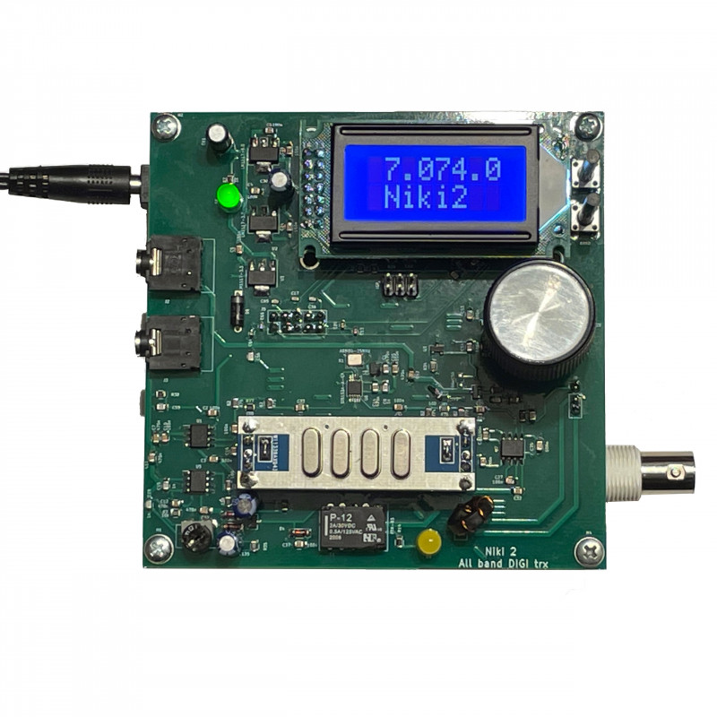
NIKI 2 is a continuation of the popular PSK NIKI 80 mini transceiver with the ability to work in all bands in the range from 1.8MHz to 30MHz with 1W power.
NIKI2 is a continuation of the popular PSK NIKI80 mini transceiver.
The main difference is the use of frequency conversion, a quartz filter and the ability to work with any digital mode, including SSTV mode. Also new is the use of frequency synthesis instead of a quartz resonator and the ability to work in all bands in the range from 1.8MHz to 30MHz.
The transceiver system is a classic frequency conversion system. The signal after the BPF bandpass filter is directed to the mixer on the SA612A system, then the quartz filter and the product detector also based on the SA612A system.
The quartz filter used in the set has a bandwidth of 3.0kHz/-6dB and an I/O impedance of 1kHz. The signal after the detector is amplified by a low-frequency amplifier on the BC847C transistor, then it is fed to the output socket for connection to the computer's sound card.
The receiver has a sensitivity of 0.18uV s/n -12dB. This is the sensitivity determined by the stable visibility of the signal on the waterfall.
The transmitting part uses the conversion path of the receiver circuit. The mixer of the receiver is used as a modulator and the product detector as a mixer of the transmitter. After the mixer, the RF signal is directed to the BPF filters, which work both on receiving and transmitting. Band selectivity rx/tx is ensured by the appropriate combination of BPF and LPF filters.
The signal selected from the BPF bandpass filters is amplified in the preamplifier on the transistor BFR106, then through the transformer T1 to the transistor BFQ19 and through the matching transformer T2 to the push-pull amplifier on the transistors BFQ19.
This arrangement ensures stable operation and low distortion. The push-pull circuit is matched to the LPF output filters by means of a T3 transformer. The quiescent currents of the BFQ19 transistors are about 30mA.
The output power of the amplifier is 1W in the 1.8 - 30MHz bands.
The VFO/BFO frequency generator is made on the Si5351 chip.
The VFO/BFO outputs are switched by software during transmit/receive.
The software provides an Atmega 328P with an 8x2 display.
The transceiver does not require additional control from the computer for proper switching of transmit/receive.
Switching is carried out using the vox m.f. system. directly from the sound card.
In the system, this is done by the amplifying and separating circuit based on the LM358 with adjustable gain level. Switching to transmit mode is signaled by a red LED.
The DIY (do it yourself) kit includes a board with soldered elements in SMD technology, elements for through-hole assembly and sockets.
Assembly instructions in English - download here
Manufacturer: RFLabo / Omega

RFlabo ŁUKASZ RUTA
Orzk 54a
95-081 Dłutów
Polska
e-mail: office@rflabo.com
Osoba odpowiedzialna:
HamRadioShop
Cezary Libert
ul. Piękna 65/67/25
93-558 Łódź
Polska
e-mail: info@hamradioshop.pl
tel. +48 602 675 847

Reference: 1030000001534
Brand: AnySecu
Dekoder CW to gotowy i uruchomiony moduł do dekodowania telegrafii z dwuliniowym wyświetlaczem LCD 2 x 8 znaków
Reference: 1030000001533
Brand: AnySecu
Forty 9-er - KIT do samodzielnego montażu miniaturowego transceivera CW QRP o mocy 4W (przy zasilaniu 12V).
Reference: 1070000001540
Brand: AnySecu
Kit wzmacniacza KF (3,5MHz - 30 MHz) 45W SSB do samodzielnego montażu (v 306)
Reference: 1090000001583
Brand: AnySecu
Kit automatycznego tunera antenowego 7x7 100W wg N7DDC na pasma 1-55MHz
Reference: 1030000001535
Brand: AnySecu
Uruchomiony oscyloskop cyfrowy JYETech DSO150 DSO-SHELL.
Reference: 1070000001509
Brand: AnySecu
DRA818V - bezprzewodowy moduł nadawczo-odbiorczy oparty na RFIC RDA1846 i pracujący w paśmie VHF
Reference: 1100000001208
Brand: AnySecu
Odbiornik SDR do samodzielnego montażu pracujący od 100kHz do 1.7GHz
Reference: 1030000001589
Brand: AnySecu
SZ Radio III CW Morse Code Trainer
Reference: 1090000001582
Brand: AnySecu
Automatyczny tuner antenowy 7x7 100W wg N7DDC na pasma 1-55MHz (ATU-100)
Reference: 1030000001536
Brand: AnySecu
KIT oscyloskopu cyfrowego DSO150-SHELL do samodzielnego montażu
Reference: 1010000000157
Brand: RFLabo / Omega
mikroQ80 – FT8 DIGI transceiver 3W DIY KIT
Reference: 1070000001587
Brand: RFLabo / Omega
Uniwersalny kompresor dynamiki / kompresor mikrofonowy
Reference: 1090000001528
Brand: RFLabo / Omega
PCB transceiver NIKI PSK - jednopasmowy minitransceiver o bezpośredniej przemianie częstotliwości przeznaczony do pracy emisją PSK
Reference: 1030000001537
Brand: AnySecu
kit pozwala na zbudowanie tunera antenowego pracującego w paśmie od 1MHz do 30MHz pozwalających na zestrojenie anten w zakresie 40 - 300 Omów.

NIKI 2 is a continuation of the popular PSK NIKI 80 mini transceiver with the ability to work in all bands in the range from 1.8MHz to 30MHz with 1W power.